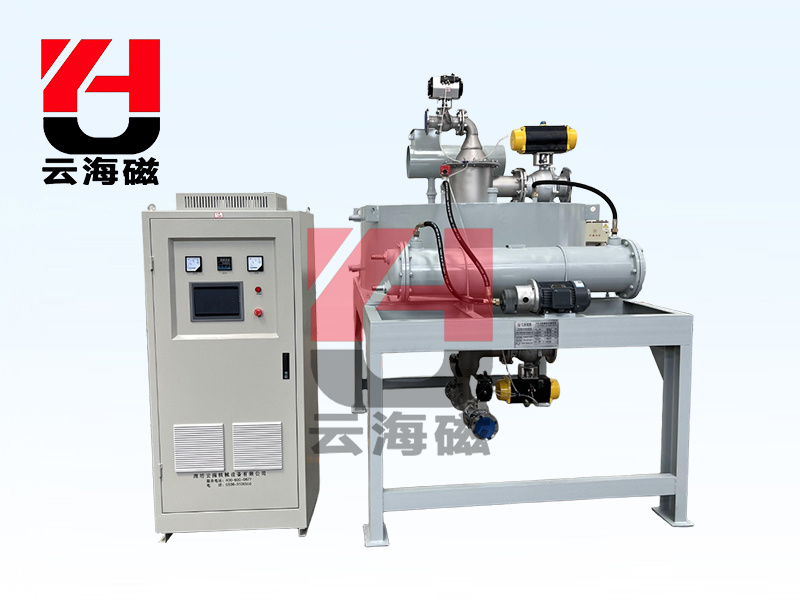
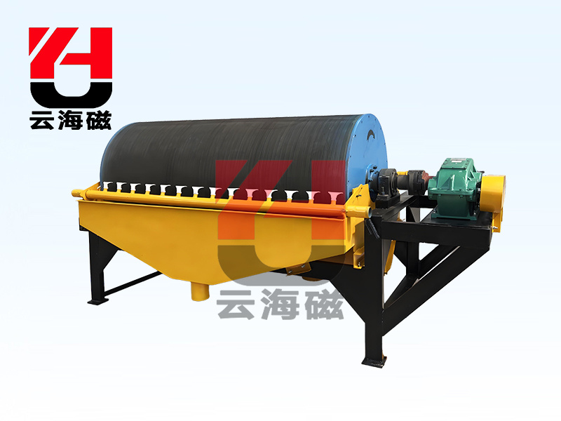
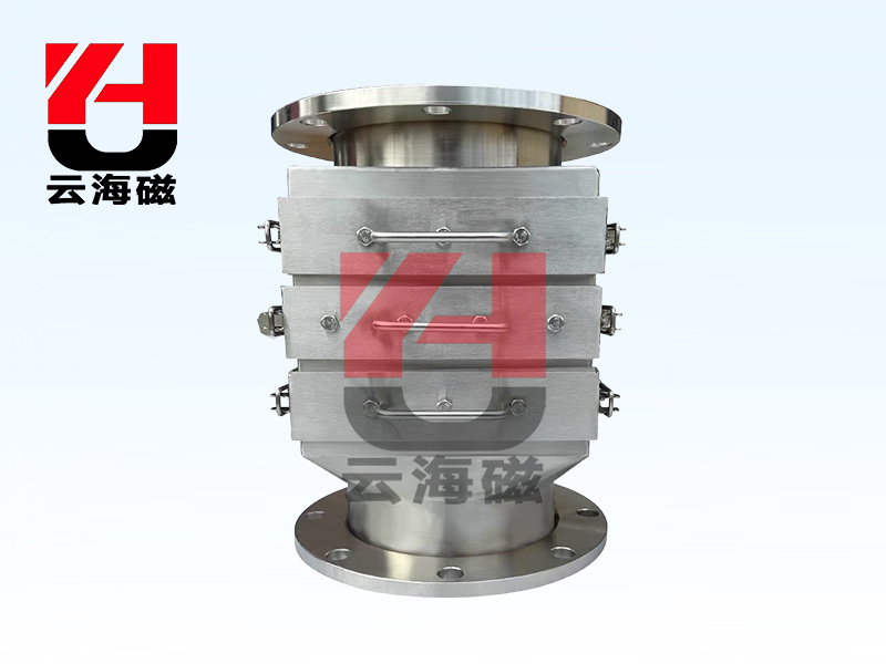
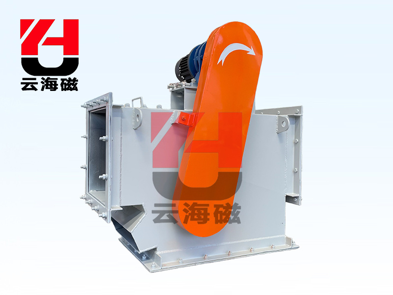
RCDEJ forced oil circulation electromagnetic iron remover
Scope of Application
Suitable for coal ports, large thermal power plants, coal, mining, metallurgy, building materials, chemical and other industries with particularly high requirements for iron removal, it can work normally in harsh environments with dust, humidity, and severe salt spray corrosion.
working principle
The body of the iron remover adopts a sealed structure, and transformer oil with good electrical insulation performance is used as the cooling medium inside. When the excitation coil is energized and generates heat, the heat is transferred to the transformer oil, which is circulated through the transformer dedicated oil pump. The transformer oil enters the cooler, and the heat is forcibly carried away by the fan. The excitation system is powered on to generate a strong magnetic field. When the scattered materials on the conveyor pass under the iron remover, the ferromagnetic impurities mixed in the materials are attracted by the magnetic field force and adsorbed on the surface of the iron remover. After the power is cut off, the iron impurities automatically fall off, thus completing the iron unloading.
Technical Features
1. Adopting transformer forced oil circulation cooling technology, the temperature rise is extremely low, and the cooling technology is mature, safe, and reliable.
2. The iron core is made of cold-rolled silicon steel sheets with high magnetic permeability and high saturation induction intensity, with a magnetic permeability much higher than that of ordinary pure iron materials, greatly reducing hysteresis loss and improving the stability of the total magnetic field.
3. The magnetic circuit of the iron remover is short, the magnetic loss is small, the magnetic field gradient is large, the iron remover has strong ability, and the iron removal rate is high.
4. The iron remover is lightweight, compact, and has good heat dissipation effect.
5. The excitation coil is completely immersed in transformer oil and forced to circulate and dissipate heat through an air cooler, resulting in a low temperature rise of the coil and greatly improving its service life.
6. The control cabinet adopts a two-stage three-phase full bridge rectifier, with stable and reliable output.
7. It has two operation modes: manual and centralized control, which can meet the requirements of various occasions.
Technical Specifications
| Model/Parameters/Project | Applicable bandwidth mm | Rated lifting height h mm | Magnetic field strength ≈ mT | Excitation power ≤ kw | Fan power KW | Overall dimensions L×Φ×H mm | Applicable belt speed≤m/s | weight kg |
| RCDEJ-10 | T1 | 1000 | 300 | 90 | 6.5 | 0.25 | 1700 × 1300 × 1210 | ≤5.8 | 2000 |
| T2 | 120 | 9.5 | 0.25 | 1700 × 1300 ×1250 | 2350 |
| T3 | 150 | 5 | 0.25 | 1750×1350×1280 | 2870 |
| RCDEJ-12 | T1 | 1200 | 350 | 90 | 9 | 0.25 | 1750×1350×1250 | 2300 |
| T2 | 120 | 14 | 0.25 | 1750 ×1350 ×1280 | 2900 |
| T3 | 150 | 20 | 0.25 | 2000×1600×1380 | 4740 |
| RCDEJ-14 | T1 | 1400 | 400 | 90 | 14 | 0.25 | 1750×1350×1280 | 2900 |
| T2 | 120 | 20 | 0.25 | 2000 × 1600 ×1420 | 4740 |
| T3 | 150 | 29 | 0.25 | 2230×1830×1450 | 6760 |
| RCDEJ-16 | T1 | 1600 | 450 | 90 | 18 | 0.25 | 2000×1600×1420 | 4900 |
| T2 | 120 | 28 | 0.25 | 2230 × 1830 × 1450 | 6000 |
| T3 | 150 | 32 | 0.25 | 2350×1950×1480 | 7950 |
|
|
|
|
| RCDEJ-18 | T1 | 1800 | 500 | 90 | 26 | 0.75 | 2250×1850×1480 | 7000 |
| T2 | 120 | 32 | 0.75 | 2350×1950×1480 | 8000 |
| T3 | 150 | 40 | 0.75 | 2460×2060×1500 | 9900 |
|
|
|
|
| RCDEJ-20 | T1 | 2000 | 550 | 90 | 30 | 0.75 | 2400×2000×1480 | 7200 |
| T2 | 120 | 39 | 0.75 | 2500×2100×1500 | 9000 |
| T3 | 150 | 4 | 0.75 | 2660×2260×1500 | 11500 |
|
|
|
|
| RCDEJ-22 | T1 | 2200 | 600 | 90 | 39 | 0.75 | 2460×2060×1500 | 10300 |
| T2 | 120 | 42 | 0.75 | 2660 × 2260 ×1520 | 11800 |
| T3 | 150 | 45 | 0.75 | 2900×2500×1520 | 12500 |
|
|
|
|
| RCDEJ-24 | T1 | 2400 | 650 | 90 | 40 | 0.75 | 2660×2260×1520 | 12800 |
| T2 | 120 | 46 | 0.75 | 2850×2450×1550 | 14980 |
| T3 | 150 | 54 | 0.75 | 3050×2650×1580 | 16500 |
|
|
|
|
Dimensions and schematic diagram

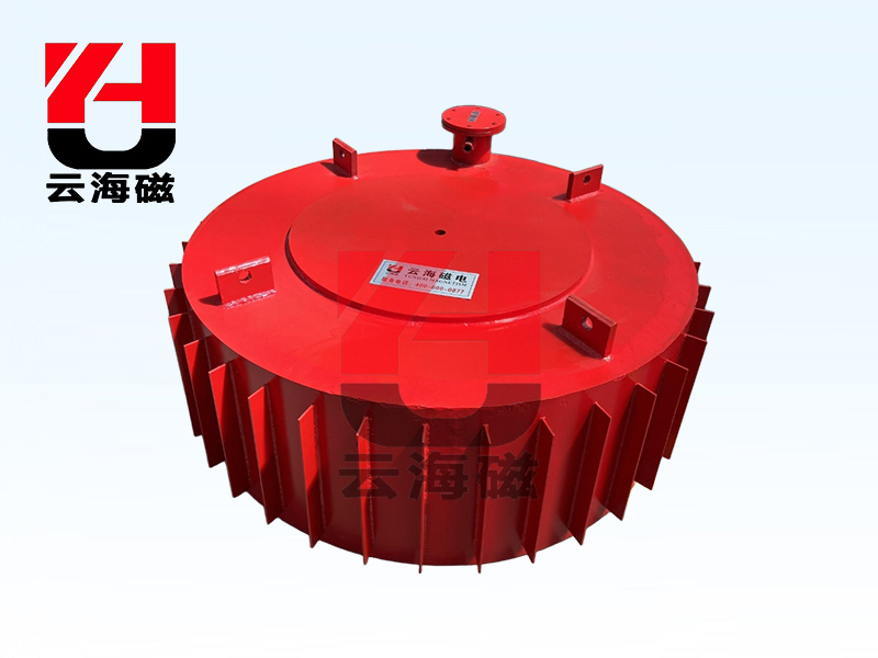
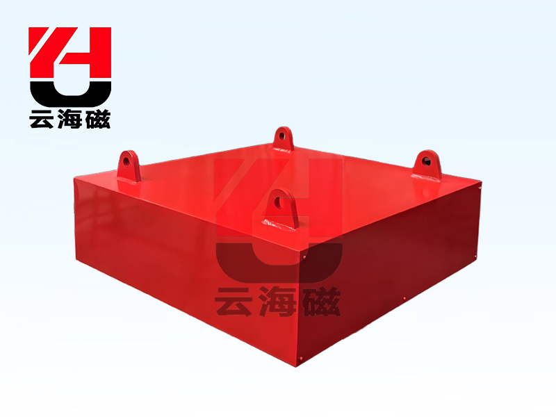
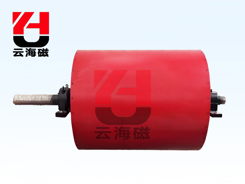
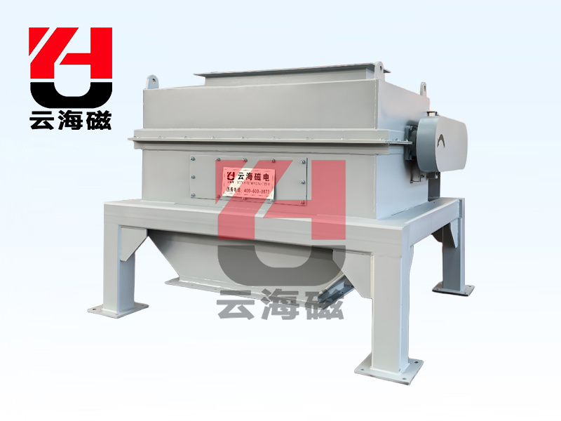
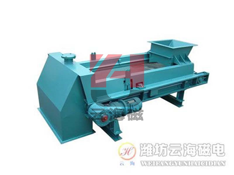
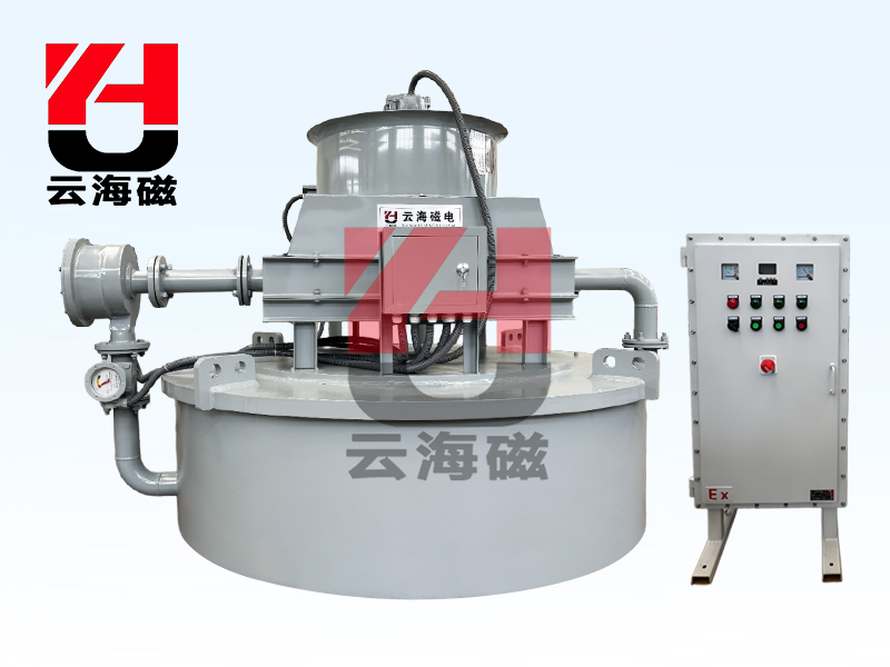
product image

 location:
 咨詢電話:400-600-0877


 HOME
HOME
 PRODUCT
 HOTLINE